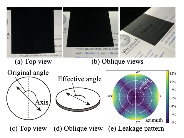
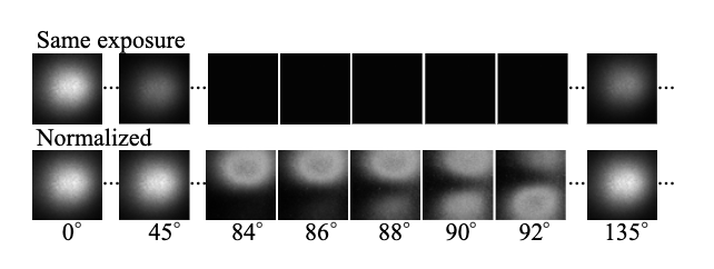
What is the effective angle of the polarizer?
It is an angle-dependent effect of the polarizer. Light leakage occurs when the light ray is oblique to the polarizer. Figure 2 below in media and in the paper shows pictures of the same scene from top and oblique views. While the LCD monitor is invisible from top view (a), it is slightly visible from certain oblique views depending on the zenith and azimuth angles (b). (c) The original angle of polarizer from top view. (d) The effective angle from oblique view. The polarizer axis is slightly declined. (e) Light leakage pattern of crossed polarizers from oblique view. This effect is angle dependent, therefore it can be used for analyzing NLOS observations.
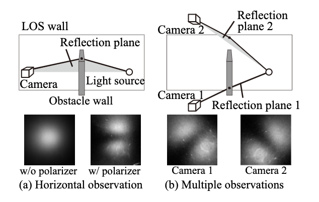
Is the reflected light polarized?
Yes, all reflections are partially polarized. Especially, when the camera is at the special angle (so called Brewster angle), the reflected light is perfectly linear polarized.
Is the the scene polarized?
No, the scene is not polarized. Although the scene is unpolarized, the reflected light off the wall is pertially polarized.
Is this superior than using specular wall?
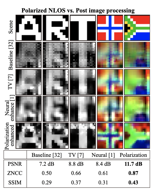
Our method always improves the performance for all reflection parameters of the wall. You can compbine our polarization technique to other techniques including putting a partial occluder and using specular wall material.
Isn’t the observation dark?
Despite the low light efficiency due to light cut off at the polarizer, the polarization cues can improve the conditioning. This is a suprising finding.
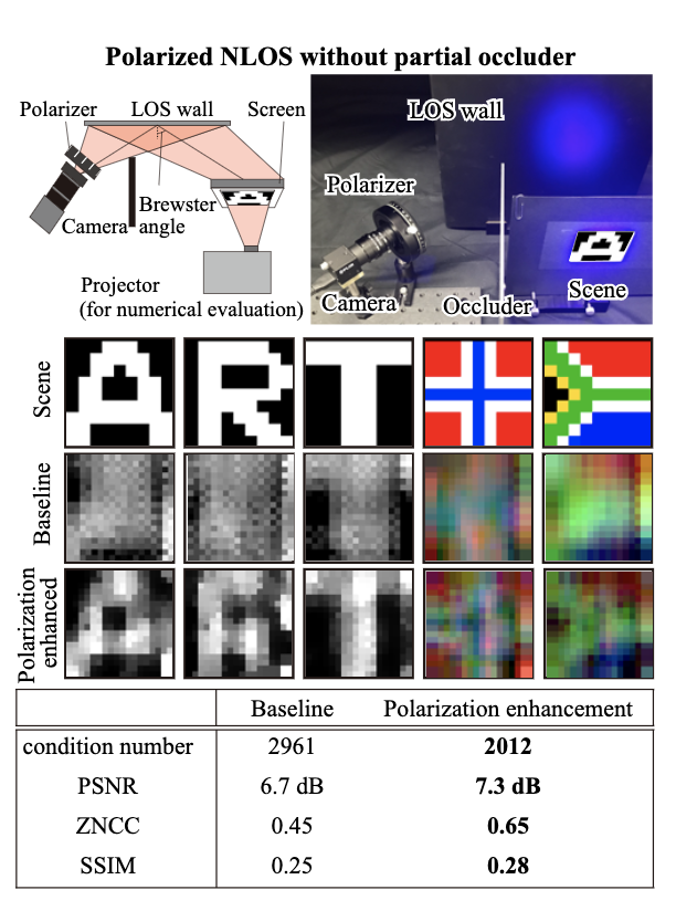
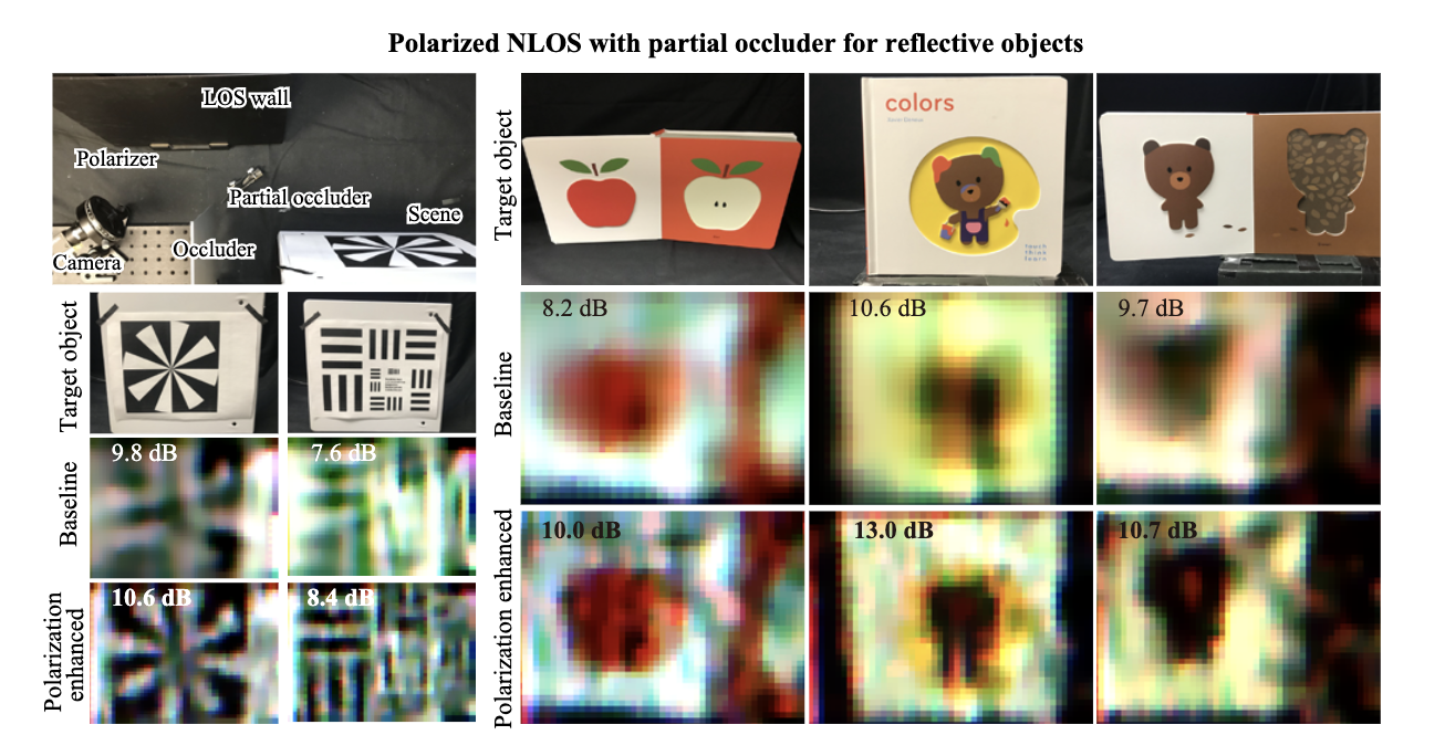 Figure 1: Results for reflective objects. Top-left: the setting of the experiment. The scene is a reflective object (not self- luminous). 1st row: The photograph of target objects. 2nd row: The recovered images by the baseline method [39]. Bottom row: The recovered images by our method. High frequency details are recovered. Clear detail of resolution charts, sharp edge of apple, and the detailed shape of bears are clearly visualized. PSNR values are calculated with homography-transformed photograph for reference.